How to create an IoT VLAN with OPNsense and TP-Link Omada (with IPv6 Prefix Delegation)
tl;dr: In this guide I'll show you how to create an OPNsense VLAN setup with a dedicated IoT VLAN, configure IPv6 prefix delegation, tag VLANs on a managed switch, and create a VLAN-aware Wi-Fi network using TP-Link Omada APs.
In this post I’ll be talking about the journey I went on to strengthen my home network by adding an isolated VLAN for IoT devices and properly assigning IPv6 addresses for all devices on my network.
This guide will cover: IPv6 prefix delegation; Creating VLAN interfaces in OPNsense; DHCP configuration; Router advertisements; Firewall isolation rules; Managed switch VLAN tagging; and Omada VLAN Wi-Fi configuration.
Table of contents
- Introduction
- Get your ISP to provision you a /60 or /56 block of IPv6 addresses
- OPNsense VLAN setup
- Configure VLANs on your managed switch
- Configure VLANs in TP-Link Omada
- Common problems/Troubleshooting
Introduction
I decided to tackle a project I had been putting off for a while: Building out a separate IoT VLAN for my home network.
Prior to this, I had been using Omada’s guest network for IoT devices in my home. But doing so caused me some headaches:
- It prevented the devices on that network from talking to each other.
- It was cluttered: Both visitor devices and IoT devices were part of the same WLAN.
- It kept me from having full visibility into the network’s firewall rules and hid activity for those devices on my network.
The Omada guest network feature is great, and I want to keep using it for when I have visitors over. I want guests to have access to our Wi-Fi, but not to our home network. And I don’t want anything running on their devices to get to see anything on our trusted network. No funny business!
Instead of using the Omada guest network for IoT devices, creating a dedicated VLAN provides better firewall control, device visibility, and network segmentation.
On a personal note, prior to this I really didn’t know much about IPv6. Frankly, I just disabled it more often than not, because I didn’t want to deal with it. It turns out that giving each device on your network a truly-global address unlocks a lot of simplicity and allows services like ZeroTier, Syncthing, and other direct-connection services to work quickly without dealing with weird legacy workarounds like IPv4 NAT.
Turns out setting this up helped me learn a bunch about IPv6, too. It was a long and arduous project but I’m glad I hunkered down and tackled it!
Hardware used
In my home network, I have the following services and devices:
- Xfinity/Comcast ISP (Residential cable)
- Motorola Nighthawk CM2000 cable modem
- OPNsense firewall/router running on an HP T730 thin client with an Intel I340-T4 NIC
- MikroTik CSS318-16G-2S+IN managed switch
- TP-Link Omada Wi-Fi APs (2x EAP610-v3, 1x EAP650-v1)
- And a bunch of devices all connected in via ethernet and over Wi-Fi
Why you should put IoT devices on a separate VLAN
I’m fairly security-minded and want to help protect the devices on my network. Smart-home devices can offer useful functionality, but I don’t believe should have full access to my trusted home LAN. How many times have we heard news stories about botnets and other things running amok in things like Smart Light Bulbs?
IoT devices should be isolated from your trusted home network because many of them:
- Receive infrequent security updates and/or run outdated firmware.
- Do naughty things, like scan your network and phone home all sorts of telemetry.
- Have glaring issues like using hardcoded admin credentials that can eventually be discovered and exploited.
Isolating IoT devices lets you use them for their convenience while preventing them from accessing your trusted network. That limits the damage blast radius in the event they’re compromised.
Before: The original network layout
Here’s the original network layout before I started.
- For simplicity’s sake, I’m only illustrating the Wi-Fi parts of the network. In reality, there’s a bunch of hard-wired devices connected up to the network.
- Network diagram icons courtesy of vrt-sheet-for-dia on GitHub, with a little of my own zhuzhing up.
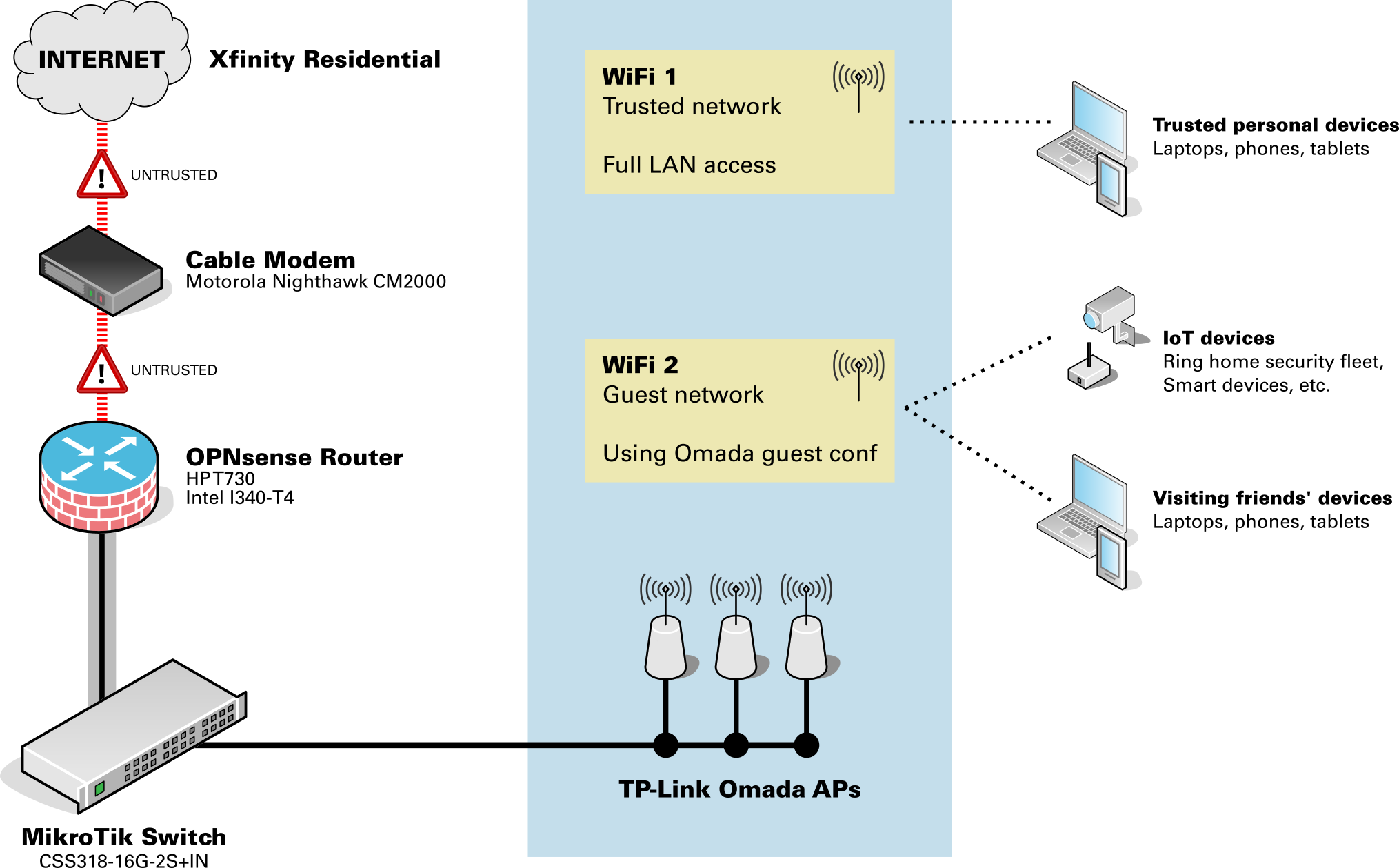
As you can see, everything non-trusted was just all tossed onto the Omada guest WLAN. There wasn’t any way to segment the devices in any meaningful way… it was either an “Fully trusted” or “Guest only” setup.
Afterwards: The improved network layout
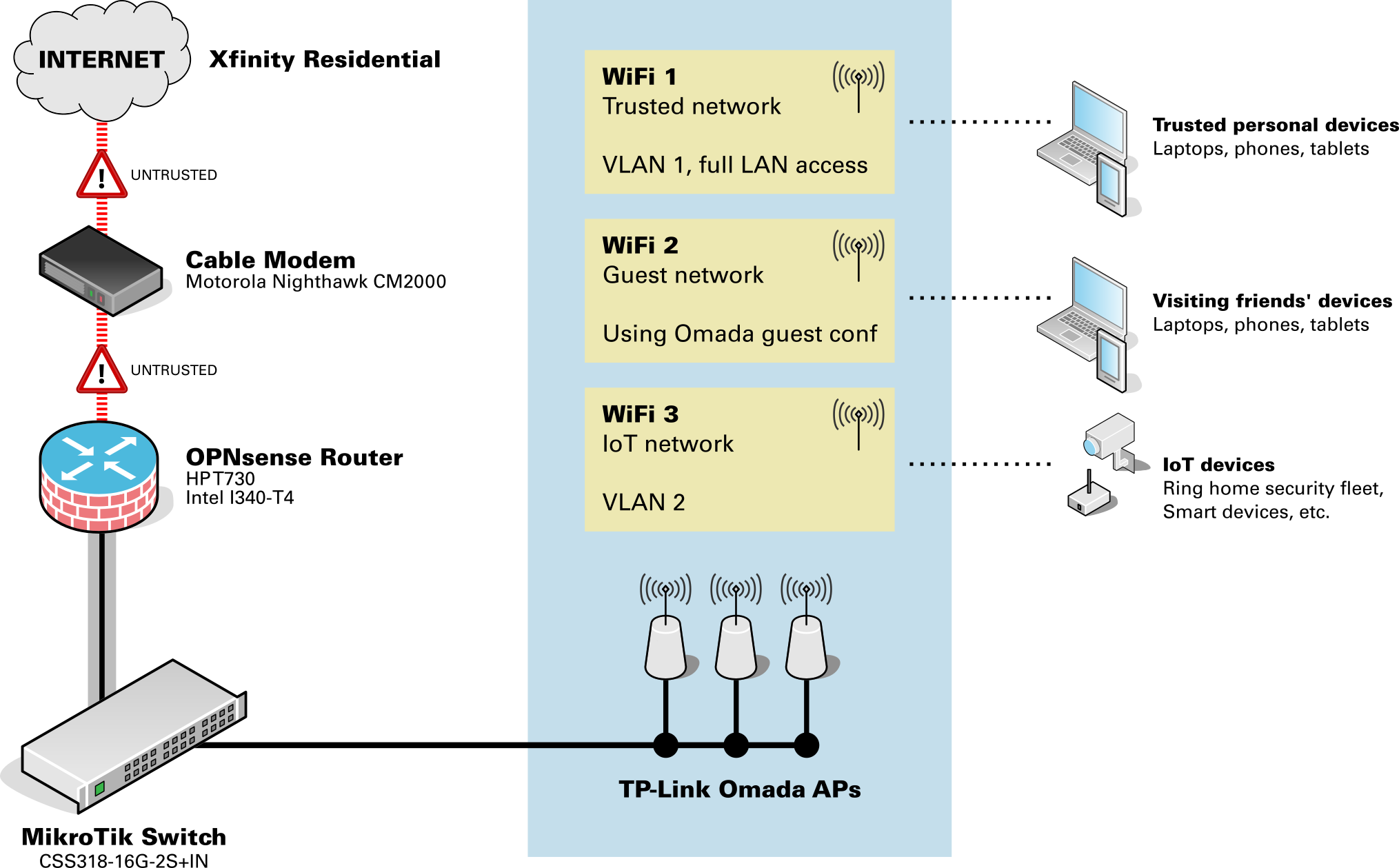
In the improved network layout:
- IoT devices are now on their own VLAN’d WLAN, isolated from the home network. They can now see each other.
- Physical network devices that are IoT related, or that I otherwise felt should be isolated (printers, etc.),are also tagged on the same VLAN to keep them isolated from the trusted network.
| Network | VLAN | Purpose |
|---|---|---|
| Trusted network | 1 | Personal computers, phones, and tablets |
| IoT network | 10 | Smart-home devices, Ring home security devices, etc. |
| Guest Wi-Fi | n/a (Omada controlled) | Visitor devices |
Get your ISP to provision you a /60 or /56 block of IPv6 addresses
As I started going through the process to enable VLANs in OPNsense, you’ll need to assign separate IPv6 address blocks for each VLAN. But this isn’t something you have full control over… these addresses aren’t something you can create yourself. They come from your ISP.
Your ISP probably delegates you a single /64 block of IPv6 addresses, because (a) it’s easy for them, and (b) most residential customers won’t need anything different as they’ll just have everything on one network anyway.
Your ISP may listen for and honor requests to issue different prefixes. Unfortunately for me, this wasn’t the case. No matter what I tried, I was only ever issued a single /64 network.
If you don’t have the /60 or /56 prefix delegation, you’ll get an error in OPNsense at the point where you enable the VLAN interface’s IPv6 Identity Association. You won’t be able to assign a Prefix ID and will get the error You specified an IPv6 prefix ID that is out of range.
Requesting the change from the ISP
Since this was only something my ISP could change, I had to work with them to request the change. This ended up taking the most time and being the most frustrating part of my journey. Working with Xfinity/Comcast’s Tier-1 support proved to be a challenge because they aren’t trained to help with IPv6 prefix delegation. Escalation paths with their support team are also tricky. I was told several times by support reps that, “The matter was being worked on and that I’d hear back from the team in 3-4 hours.” But after a day went by I had to follow up with support again, starting all over in the explanation each time. I had to repeat that cycle for several days before I got a ticket number for my request.
In total, it took about a dozen calls to Xfinity support over the course of one week to get this changed. Eventually, they did provision me a /60, and I was up and running!
Validating the prefix your ISP is issuing
To validate the IPv6 prefix you’re receiving, go to OPNsense and navigate to System > Log Files > General. Search for keyword prefix under log level Notice. Look at the most recent log entries and look at the last digits to see what network prefix you’re being issued. You want to see either /60 or /56.
dhcp6c_script: REQUEST on igb0 prefix now 2001:db8:1234:5670::/56    # Good
dhcp6c_script: REQUEST on igb0 prefix now 2001:db8:1234:5670::/60    # Good
dhcp6c_script: REQUEST on igb0 prefix now 2001:db8:1234:5670::/64    # Not good
A /56 is good, too! That means you’re being issued 256 different network groups. I requested a /60 to be more conservative, as the 16 different networks provided by the /60 should be more than sufficient for my needs. I also wanted to be conservative with my request to Xfinity in case they pushed back on the larger allocation.
OPNsense VLAN setup
This section walks through the complete process of configuring a VLAN in OPNsense. We’ll create the VLAN interface, assign IPv4 and IPv6 networks, enable DHCP, and configure router advertisements so devices can obtain IPv6 addresses.
The steps below assume you already have:
- A managed switch capable of VLAN tagging
- Wi-Fi access points that support VLANs
- An IPv6 prefix delegation from your ISP (see above)
Once your ISP is providing you a /56 or /60, you can continue actually setting up the VLANs on your network.
We’ll start by building that out in OPNsense, then roll out the VLAN elsewhere on the network.
Create the IoT VLAN in OPNsense
Within OPNsense, navigate to Interfaces > Devices > VLAN.
- Parent interface:
igb1 (LAN)- (Or whatever your LAN interface is)
- VLAN Tag:
10- (I used
10here, but you can use something different if you’d like. Just be sure you keep this value consistent with the steps later on in this guide.)
- (I used
Add the new VLAN interfaces and enable them.
Assign the VLAN interface
First, add the new interface.
Navigate to Interfaces > Assignments.
- Assign a new interface
- Device:
vlan01
- Device:
Then, enable the interface.
Navigate to Interfaces > VLAN01.
- Basic
- Enable interface =
Checked
- Enable interface =
- Generic
- IPv4 Config Type =
Static IP - IPv6 Config Type =
Identity association
- IPv4 Config Type =
- Static IPv4 Config
- IPv4 address = Provide an IP range here to use for the VLAN devices, like
192.168.10.1/24
- IPv4 address = Provide an IP range here to use for the VLAN devices, like
- IPv6 Identity Association
- Parent interface =
WAN - Assign Prefix ID =
1
- Parent interface =
If at this step you get the error “You specified an IPv6 prefix ID that is out of range,” then your ISP might be provisioning you a /64 IPv6 instead of the /60 or /56.
Configure DHCP for the VLAN
Adapt the values here to suit your needs. For this example, we’re using 192.168.10.1/24 as the address pool, and I’m giving .100-.254 to be open slots of the DHCP pool. We’ll keep .2-.99 for static IP reservations. You can of course change that allocation however you want!
Navigate to Services > Dnsmasq DNS & DHCP > DHCP ranges.
- Interface = VLAN10
- Start address =
192.168.10.100 - End address =
192.168.10.254
- Start address =
Enable DHCP server/service on new interfaces
Navigate to Services > Dnsmasq DNS & DHCP > General.
- Interface:
LAN+ Add newVLANnetwork (it’s a multi-select field)
Enable IPv6 router advertisements
Turns out, the default OPNsense configuration doesn’t enable this for you on the LAN. Enabling this (even just for the LAN network) fixed a bunch of weird issues I was seeing on my network!
Next, we’ll enable router advertisements (which provides IPv6 routing and address information for devices on your network.
Navigate to Services > Router Advertisements.
Make an RA for the base LAN.
New:
- Enabled =
Checked - Interface =
Your LAN - Mode =
Assisted
Then, make an RA for each VLAN you created earlier.
New:
- Enabled =
Checked - Interface =
VLAN10 - Mode =
Assisted
Create firewall rules
There’s a few schools of thought here on how you can secure the VLAN traffic. We’ll of course prevent the VLAN from initiating connections to the trusted network, but as far as outbound traffic goes, we could…
- Prevent all outbound traffic on all ports and protocols, except on specific ports.
- The most secure, but the most time consuming to set up and maintain over time.
- Allow all outbound traffic on all ports and protocols, except to protected networks and addresses.
- Secure as long as you are careful!
I wanted to naturally go with “total blacklist except what I specifically allow,” but then I realized I’d be forever maintaining the list of ports that need to be open for all these random IoT devices to operate. So, I opted for the second choice.
OPNsense allows for the creation of Aliases so we can assign a single place to store all the trusted network addresses and network interface names. Aliases can only hold items of a certain type, so we’ll be making three of them:
- A list of all trusted networks.
- A list of all trusted IP addresses.
- A joint list combining all items in #1 and #2, which we’ll apply in the firewall rules.
First, we’ll create an Alias for networks to trust.
Navigate to Firewall > Aliases > Create.
- Enabled =
Checked - Name =
TRUSTED_NETWORKS - Type =
Network(s) - Content =
__lan_network - Description =
Specific networks to trust
Then, the Alias for IP addresses.
Navigate to Firewall > Aliases > Create.
- Enabled =
Checked - Name =
TRUSTED_ADDRS - Type =
Host(s) - Content =
192.168.1.1(or your OPNsense router management IP), then the IP address of any other management devices or other things you want to block. - Description =
Specific IP addresses to trust
Create an Alias to join those two.
Navigate to Firewall > Aliases > Create.
- Enabled =
Checked - Name =
TRUSTED_COMBINED - Type =
Network Group - Content =
TRUSTED_ADDRS,TRUSTED_NETWORKS - Description =
The combined group of all trusted entities
Next, we’ll set up the firewall rules.
Start by allowing traffic out of VLAN.
Navigate to Firewall > Rules > [Your VLAN Interface].
Add rule:
- Action =
PASS - Interface =
[Your VLAN Interface] - Direction =
IN - TCP/IP Version =
IPv4+IPv6 - Protocol =
ANY - Source =
[Your VLAN Interface] net - Destination =
ANY - Description =
Allow [Your VLAN Interface] out to any internet destination
Then, block traffic from the VLAN to the joint alias of protected network resources.
Navigate to Firewall > Rules > [Your VLAN Interface].
Add rule:
- Action = Either
REJECTorBLOCK(see note below) - Interface =
[Your VLAN Interface] - Direction =
IN - TCP/IP Version =
IPv4+IPv6 - Protocol =
ANY - Source =
[Your VLAN Interface] net - Destination =
TRUSTED_COMBINED - Description =
Block [Your VLAN Interface] to protected network entities
Then, move the block rule above the allow rule.
About the block rule:
- Make sure that the block rule is ABOVE the allow rule.
- Use
REJECTif you want fast rejections upon accessing protected resources. That’s good for devices on internal networks so the devices don’t hang forever waiting to timeout when they hit the firewall. UseBLOCKif you just want devices trying to reach protected resources to never hear back. It’s more secure per-se, but could lead to long timeouts and possible network congestion from IoT devices waiting on hold.
Configure VLANs on your managed switch
We probably have different devices here, so you’ll need to follow whatever instructions your switch’s vendor provides for setting up the VLANs.
The most important parts are:
- Set up a base VLAN for trusted traffic (I used VLAN
1). - Tag any physical ports for devices that must be VLAN’d (I put our network printer on the IoT VLAN.)
- Tag any physical ports for Omada APs to have both VLAN
1and10.
Configure VLANs in TP-Link Omada
To get Wi-Fi devices onto this new VLAN, you’ll need to create a new WLAN for them. Use a completely separate, strong password for this network.
While setting up the new WLAN, under Advanced Settings, use:
- VLAN =
Custom - Add VLAN =
By VLAN ID,10
When you connect devices, check that their IPv4 addresses are part of the new VLAN range. You’ll also want to check the IPv6 addresses and see that their addresses are part of the VLAN’s group, indicated by the different prefix (in this case, b500 for devices in the trusted LAN, and b501 for devices in the IoT VLAN with prefix 1).
Device on Trusted LAN    2001:db8:100:b500::25
Device on IoT VLAN       2001:db8:100:b501::25
Common problems/Troubleshooting
Error: “IPv6 prefix ID is out of range”
This usually means your ISP is only delegating a /64 IPv6 prefix instead of a /60 or /56. OPNsense requires a larger delegated prefix when assigning IPv6 subnets to multiple VLAN interfaces.
Solution:
- Contact your ISP and request a
/60or/56prefix delegation (see above). - Confirm the prefix using
System > Log Files > Generalin OPNsense (see above).
VLAN Wi-Fi devices are not receiving IP addresses
Check the following:
- The VLAN ID configured on the Omada WLAN matches the VLAN tag on the switch.
- The switch port connected to the AP is configured as a tagged trunk.
- DHCP is enabled for the VLAN interface in OPNsense.
IoT devices cannot see each other
Make sure Client Isolation is disabled on the VLAN WLAN in Omada.